- 您现在的位置:买卖IC网 > Sheet目录17352 > AS1323-30 EB (ams)BOARD EVAL AS1323-30
AS1323
Datasheet - P a c k a g e D r a w i n g s a n d M a r k i n g s
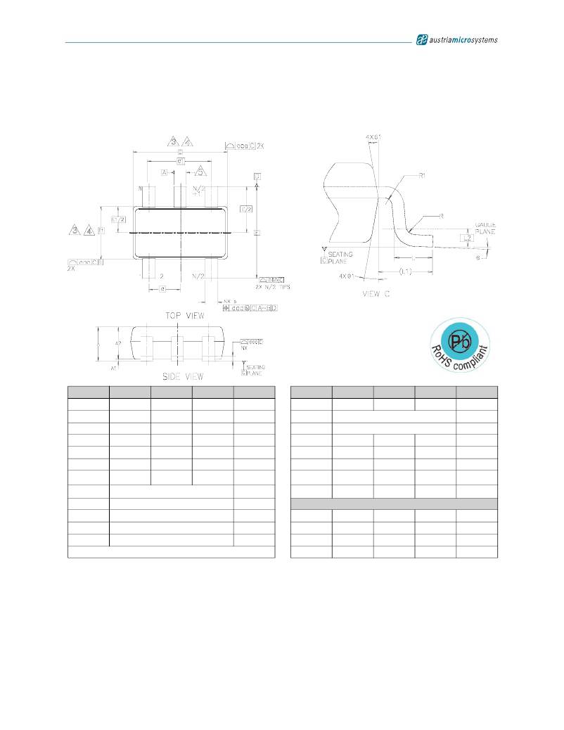
10 Package Drawings and Markings
The device is available in an TSOT23-5 package.
Figure 22. TSOT23-5 Package
Symbol
Min
Typ
Max
Notes
Symbol
Min
Typ
Max
Notes
A
1.00
L
0.30
0.40
0.50
A1
A2
b
b1
0.01
0.84
0.30
0.31
0.05
0.87
0.35
0.10
0.90
0.45
0.39
L1
L2
N
R
0.10
0.60REF
0.25BSC
5
c
0.12
0.15
0.20
R1
0.10
0.25
c1
0.08
0.13
0.16
θ
0o
4o
8o
D
E
E1
e
e1
2.90BSC
2.80BSC
1.60BSC
0.95BSC
1.90BSC
3,4
3,4
3,4
θ 1
aaa
bbb
ccc
4o 10o 12o
Tolerances of Form and Position
0.15
0.25
0.10
ddd
0.20
Notes:
1. Dimensions are in millimeters.
2. Dimension D does not include mold flash, protrusions, or gate burrs. Mold flash, protrusions, and gate burrs shall not exceed
0.15mm per end. Dimension E1 does not include interlead flash or protrusion. Interlead flash or protrusion shall not exceed 0.15mm
per side. Dimensions D and E1 are determined at datum H.
3. The package top can be smaller than the package bottom. Dimensions D and E1 are determined at the outermost extremes of the
plastic body exclusive of mold flash, tie bar burrs, gate burrs, and interlead flash, but include any mismatches between the top of the
package body and the bottom. D and E1 are determined at datum H.
Revision 1.07
11 - 14
发布紧急采购,3分钟左右您将得到回复。
相关PDF资料
AS1323-27 EB
BOARD EVAL AS1323-27
RE-2409S/H
CONV DC/DC 1W 24VIN 09VOUT
EGM06DRMN
CONN EDGECARD 12POS .156 WW
LQW2UAS12NJ00L
IND 12NH 1000MA SRF 3300MHZ 1008
A9CAG-0604F
FLEX CABLE - AFG06G/AF06/AFE06T
ASPI-0615FS-220M-T2
INDUCTOR SHLD POWER 22.0UH SMD
AD581LH
IC VREF SERIES PREC 10V TO-5-3
MIC5801BV TR
IC DRVR LATCH 8BIT PAR IN 28PLCC
相关代理商/技术参数
AS1323-30-EB
制造商:ams 功能描述:AS1323-30 Evaluation Board
AS1323-33
制造商:AMSCO 制造商全称:austriamicrosystems AG 功能描述:1.6レA Quiescent Current, Single Cell, DC-DC Step-Up Converter
AS1323-33 EB
功能描述:BOARD EVAL AS1323-33 RoHS:否 类别:编程器,开发系统 >> 评估板 - DC/DC 与 AC/DC(离线)SMPS 系列:- 产品培训模块:Obsolescence Mitigation Program 标准包装:1 系列:True Shutdown™ 主要目的:DC/DC,步升 输出及类型:1,非隔离 功率 - 输出:- 输出电压:- 电流 - 输出:1A 输入电压:2.5 V ~ 5.5 V 稳压器拓扑结构:升压 频率 - 开关:3MHz 板类型:完全填充 已供物品:板 已用 IC / 零件:MAX8969
AS1323-33-EB
制造商:ams 功能描述:AS1323-33 Evaluation Board
AS1323-BTTT-27
功能描述:IC REG BOOST SYNC 2.7V TSOT23-5 RoHS:是 类别:集成电路 (IC) >> PMIC - 稳压器 - DC DC 开关稳压器 系列:- 设计资源:Design Support Tool 标准包装:1 系列:- 类型:升压(升压) 输出类型:固定 输出数:1 输出电压:3V 输入电压:0.75 V ~ 2 V PWM 型:- 频率 - 开关:- 电流 - 输出:100mA 同步整流器:是 工作温度:-40°C ~ 85°C 安装类型:表面贴装 封装/外壳:SOT-23-5 细型,TSOT-23-5 包装:剪切带 (CT) 供应商设备封装:TSOT-23-5 其它名称:AS1323-BTTT-30CT
AS1323BTTT-27
制造商:AMS 功能描述:IC STEP-UP DC/DC CONVERTER 5-TSOT-23 制造商:AMS 功能描述:IC, STEP-UP DC/DC CONVERTER, 5-TSOT-23; Primary Input Voltage:1.2V; No. of Outputs:1; Output Voltage:2.7V; Output Current:100mA; No. of Pins:5; Operating Temperature Min:-40C; Operating Temperature Max:85C; Output Current Max:100mA;RoHS Compliant: Yes
AS1323-BTTT-30
功能描述:IC REG BST SYNC 3V 0.1A TSOT23-5 RoHS:是 类别:集成电路 (IC) >> PMIC - 稳压器 - DC DC 开关稳压器 系列:- 标准包装:50 系列:- 类型:升压(升压) 输出类型:可调式 输出数:1 输出电压:5 V ~ 25 V 输入电压:2.3 V ~ 5.5 V PWM 型:电流模式 频率 - 开关:600kHz,1.2MHz 电流 - 输出:1A 同步整流器:无 工作温度:-40°C ~ 85°C 安装类型:表面贴装 封装/外壳:8-TSSOP,8-MSOP(0.118",3.00mm 宽) 包装:管件 供应商设备封装:8-MSOP
AS1323BTTT-30
制造商:AMS 功能描述:IC STEP-UP DC/DC CONVERTER 5-TSOT-23 制造商:AMS 功能描述:IC, STEP-UP DC/DC CONVERTER, 5-TSOT-23; Primary Input Voltage:1.2V; No. of Outputs:1; Output Voltage:3V; Output Current:100mA; No. of Pins:5; Operating Temperature Min:-40C; Operating Temperature Max:85C; Output Current Max:90mA ;RoHS Compliant: Yes
